Hello!
After one of the craziest summers I have seen since I have been on this job, I finally got a chance last week to get back into setting up my AutoCAD P&ID software. It took a little while just to remember where I had left off, but before long I was making progress again toward getting things set up to our company standards.
In my test project, I ran into one particularly challenging operation. One that should have been relatively easy. I wanted to create a simple instrument loop where, after placing a primary instrument on a line, all related instruments connected to it took on the same instrument loop number.

This turned out to be more of a challenge than I thought it should be. None of the signal lines, or general instrument symbols contained any of the necessary acquisition rules to make this happen. I searched the internet, including the Autodesk Community forum for AutoCAD P&ID. There was no easy workflow described, and in fact several of the posts I read said that this is something that can be fairly difficult to achieve.
I don’t like to be told that my software can’t do something I need it to do. I take it as a personal challenge, as I did this past week. I did find a video that showed the steps needed for these rules, but the forum thread I found it in went on to report that it no longer worked. So, I used this as a starting point and did some trial and error testing with rules and custom properties. After a few hours, I finally managed to put together a workflow that gave me what I was looking for. As with all of my tips, I will say that this may not be the best, or even the only way to do this.
Rather than try to describe each individual step here, I have recorded a short video of the steps I used too to accomplish this. Note that the property names can be whatever you want them to be, but they should not be the same from one class to another. Also, I suggest writing the names down so you can easily remember them when moving back and forth between class definitions. So, without further ado, here is the video.
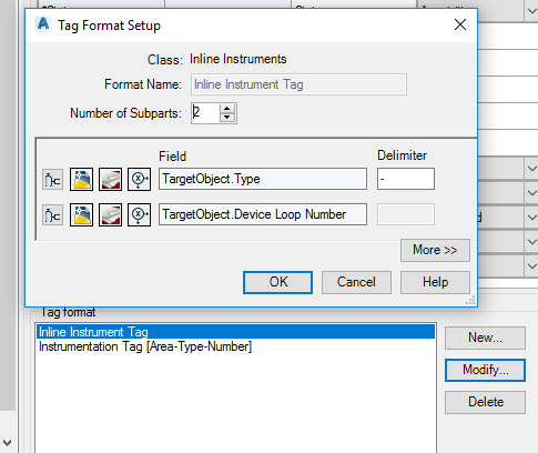
In the video, I neglected to mention that I also created a couple of new Tag Formats. The first was created under Inline Instruments, as shown here:
The next was under General Instrument Symbols, as so:

I set these both to the default for these classes by setting TagFormatName:

With all of these pieces in place the workflow performed as I hoped it would. One more hurdle passed. I hope this helps you at least in some small way. Thank you and as always…
Enjoy!
“Autodesk ® screen shots reprinted with the permission of Autodesk, Inc. Autodesk ® , AutoCAD® , DWG, the DWG logo, Vault ®, Autocad Electrical ® and Inventor ® are registered trademarks or trademarks of Autodesk, Inc., and/or its subsidiaries and/or affiliates in the USA and other countries.” Programs and programmers’ information used with permission. Thanks guys!

Hi,
I managed to get that connection right but when I try to link it with a control valve it won’t work.
Also have you managed to get this loops correct in a report?
Thanks
LikeLike
Daniel, thanks for visiting my blog. I’m afraid that as a company we have abandoned the AutoCAD P&ID all together. Not the direction we want to go. This test run with these loops was about as far as I got. Have you posted your question in the Autodesk forums for P&ID? There are at least two Expert Elites that I know who frequently answer questions in there.
LikeLike
Thanks for replying its been useful information.
Do you maybe have there emails so I can ask them ? if not it’s okay I will drop them a message.
Regards
LikeLike
I do not have email for them, but in the Autodesk forums look for Craig Wood or David Wolfe.
LikeLike
Great ! Thank you very much!
LikeLike